
email: calmansys@yahoo.com
Pipes Tubing & Wiring

Why Use Tubing Over Pipe?
Compression tube fittings
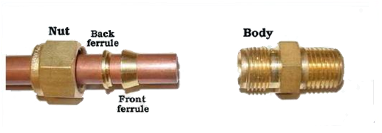
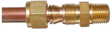
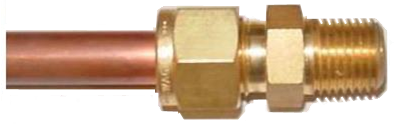


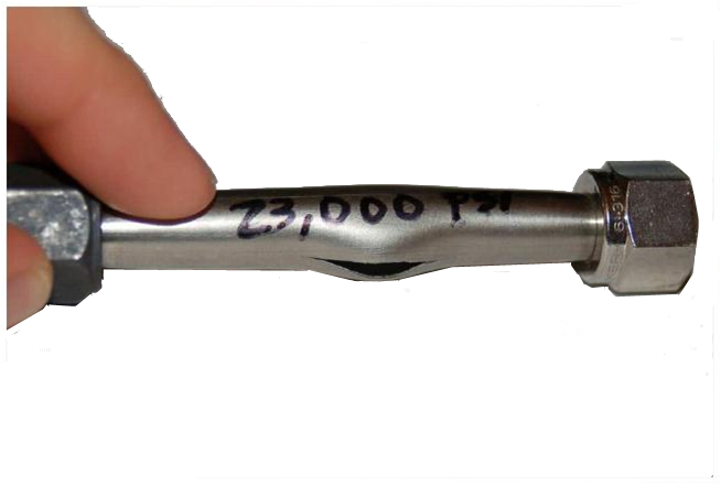
Neither compression fitting on either side of the tube leaked during the test, despite the liquid pressure reaching a peak of 23,000 PSI before rupturing the tube
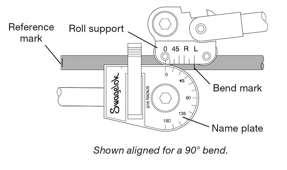
As already noted, tube bendability is one of the outstanding advantages of using tubing. Careful measurement and accurate bending are essential to achieving desired installation requirements including the achievement of a correct tube and fitting connection.
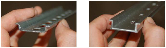
1. Use a tube bender when bending tubing. 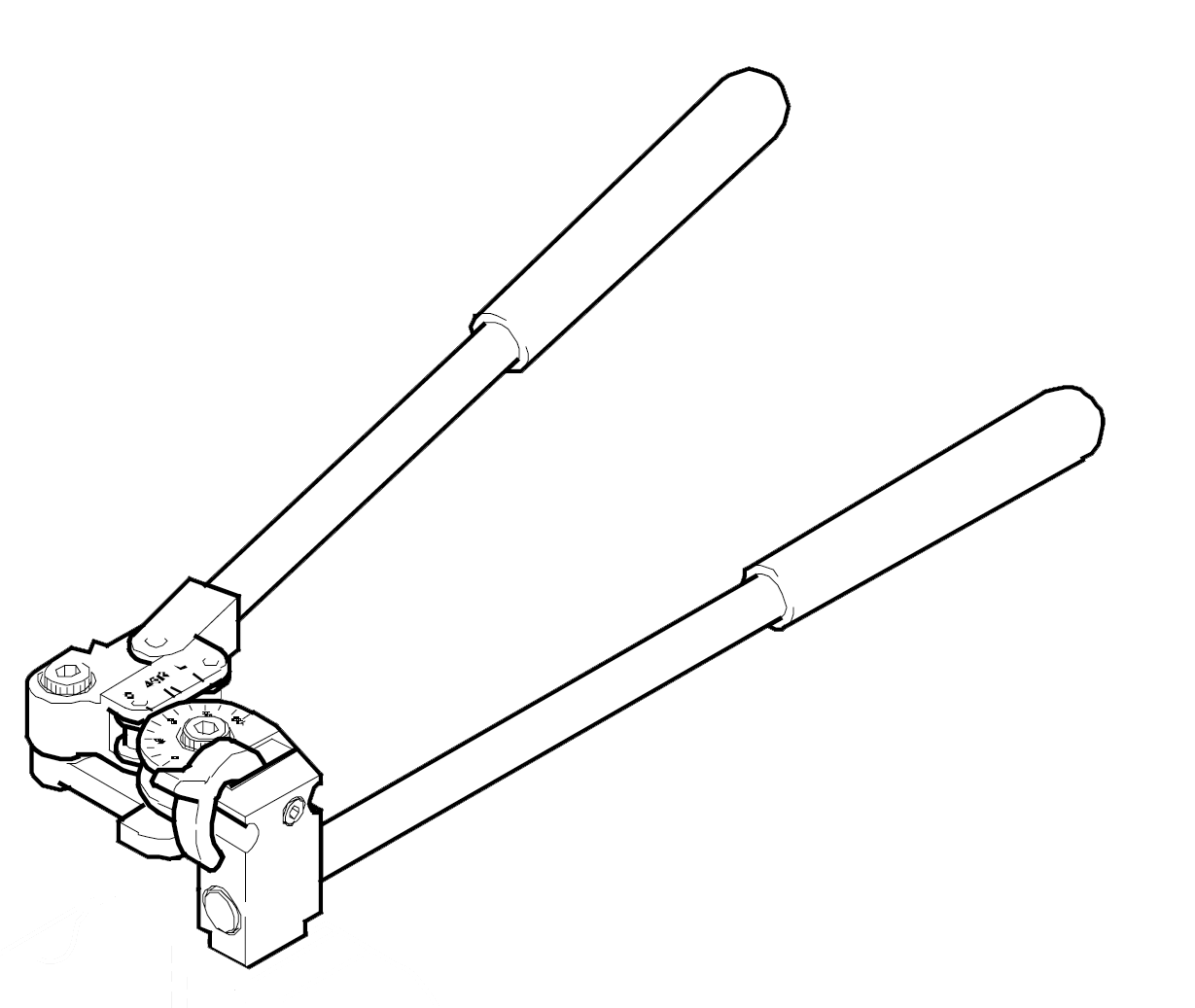
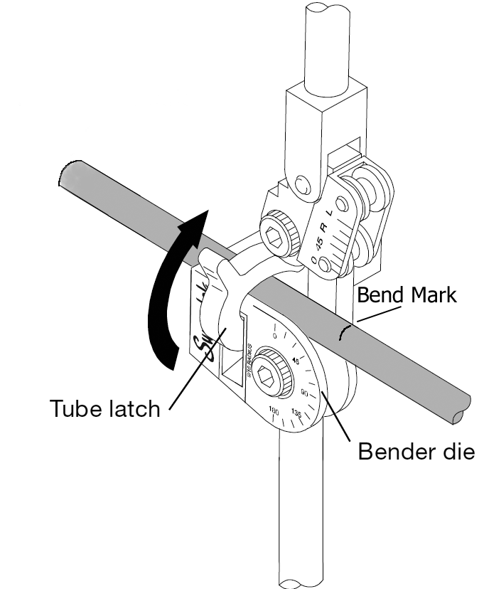
In order to prevent the problems of flattening, kinking, or wrinkling, use a tube bender and ensure tubing is tightly locked in the bender.
 Bending Problems
|
Fractional, inches |
||
|
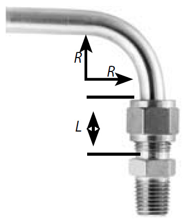
T Tube OD |
R Bend Radius |
L |
|
1/4 |
9/16 & 3/4 |
13/16 |
|
5/16 |
15/16 |
7/8 |
|
3/8 |
15/16 |
15/16 |
|
1/2 |
1 1/2 |
1 3/16 |
|
Metric, mm |
||
|
T Tube OD |
R Bend Radius |
L |
|
6 |
15 |
21 |
|
8 |
24 |
23 |
|
10 |
24 |
25 |
|
12 |
38 |
31 |
Before marking the tubing for bending, it is important that a complete layout be identified including consideration, where appropriate of the use of expansion loops, offsets, staggered union locations, and vertical ganging. Always allow sufficient access to utilities and other equipment requiring maintenance. A goal in tube routing is to eliminate as many connections as possible. Connections invite leaks, and leaks are problematic.
Example: Assume the following layout is required for tubing:

Required Length of Tubing
Marking the Tubing
Mark the tubing based on the brackets [ ] shown above:


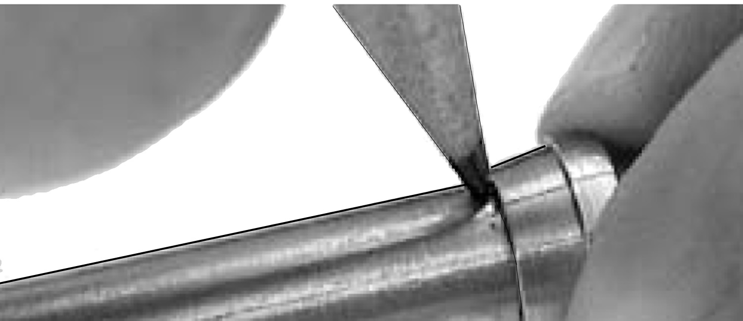
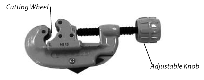
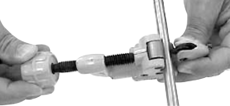
Cutting the Tube End
To insure a good joint, tube must be cut off square. This can be accomplished with either a tube cutter or hacksaw.

Burrs forms after using Tube Cutter Deburring Tool
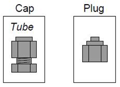
Types of Connectors
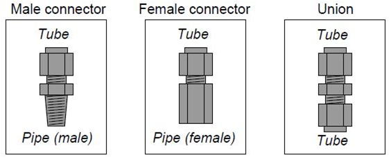
If a tube union joins together different tube sizes rather than tubes
it is called a reducing union.
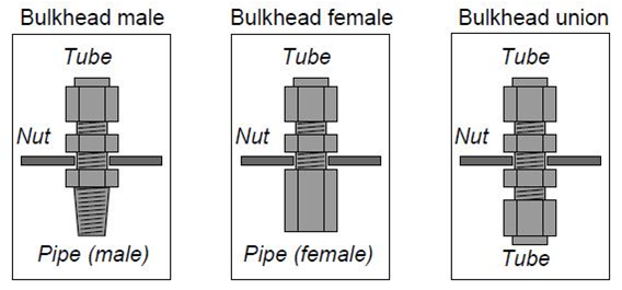
Bulkhead fittings are designed to fit through holes drilled in panels or enclosures to provide
a way for a fluid line to pass through the wall of the panel or enclosure.
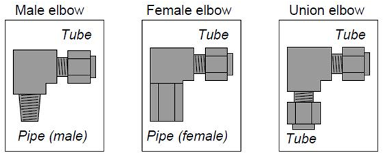
Tubing elbows are tube connectors with a bend. These are useful for making turns in tube runs without having to bend the tubing itself. Like standard connectors, they may terminate in male pipe thread, female pipe threads, or in another tube end.
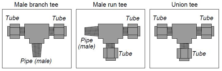
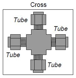
Tee fittings join three fluid lines together. Tees may have one pipe end and two tube ends (branch tees and run tees), or three tube ends (union tees).The only difference between a branch tee and a run tee is the orientation of the pipe end with regard to the two tube ends
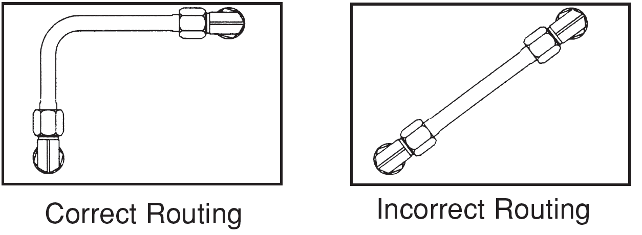
Routing of Bend
;Routing of lines is probably the most difficult yet most significant of these system design considerations. Proper routing involves connecting one point to another through the most logical path.
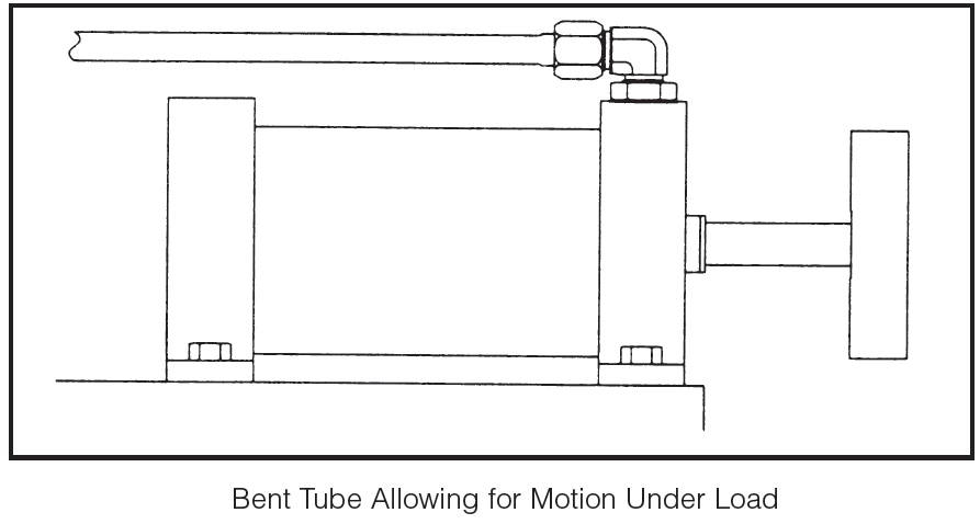
Avoid excessive strain on joints - A strained joint will eventually leak.
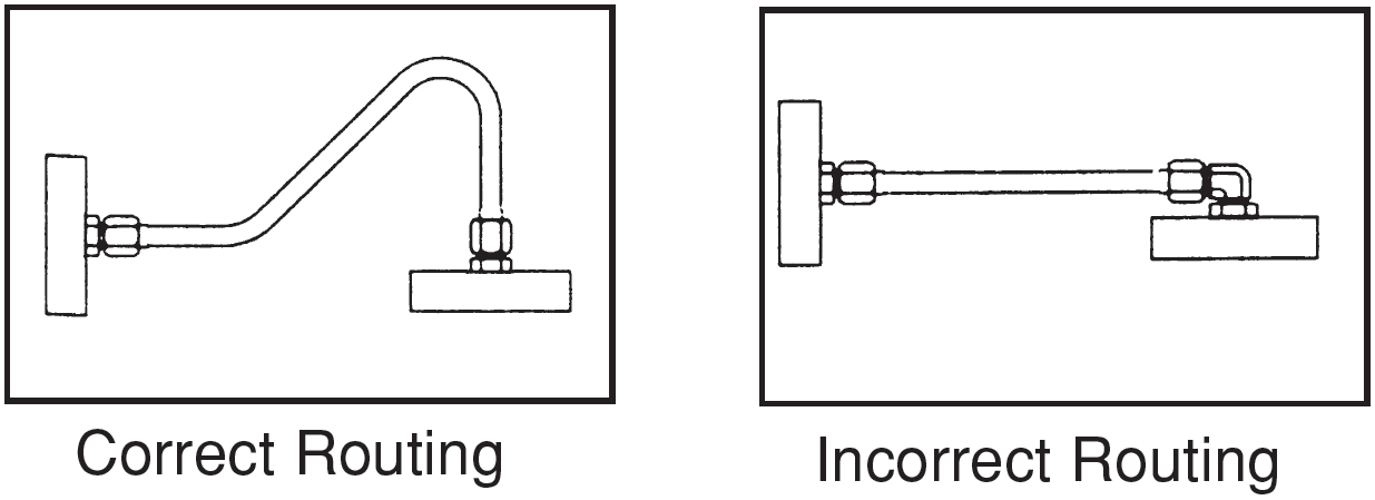
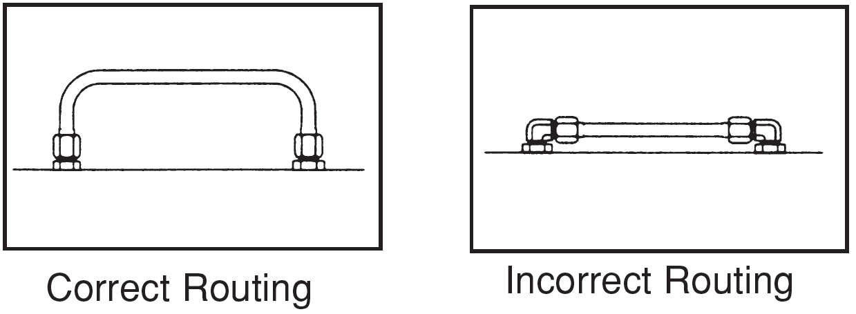
Allow for expansion and contraction - Use a “U” bend to allow for expansion and contraction.
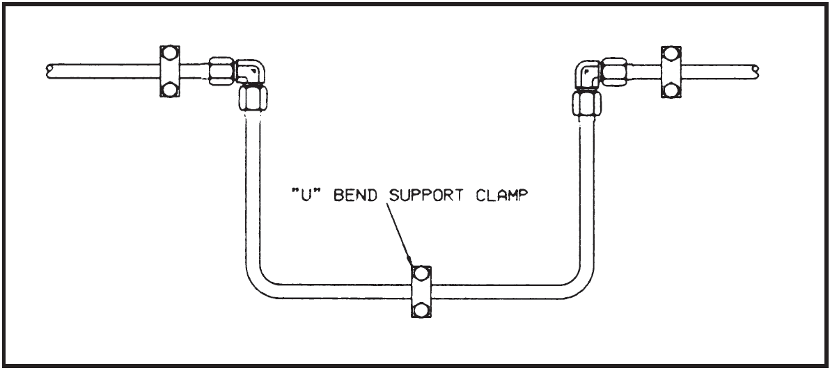
U-Bend Allowing for Expansion and Contraction
Keep tube lines away from components that require regular maintenance.
Have a neat appearance and allow for easy trouble shooting, maintenance and repair.
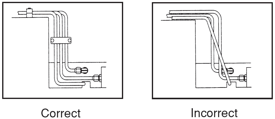
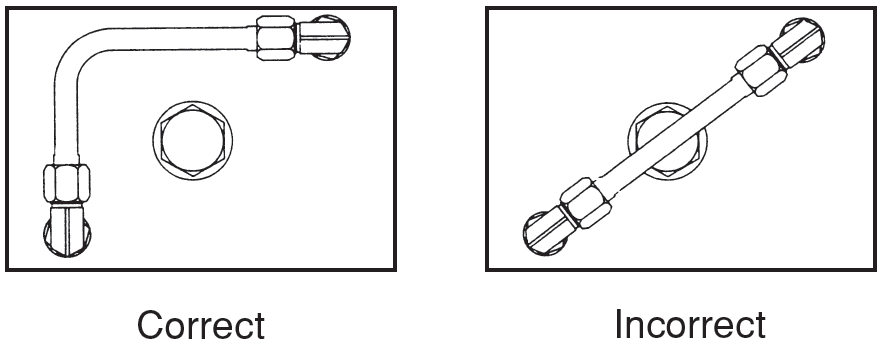
Offset Bends and Stagger Union Locations
Offset bends are used to increase accessibility to tube fitting unions for maintenance purposes. When offsetting in a ganged run, stagger the union locations to further ensure ease of access.
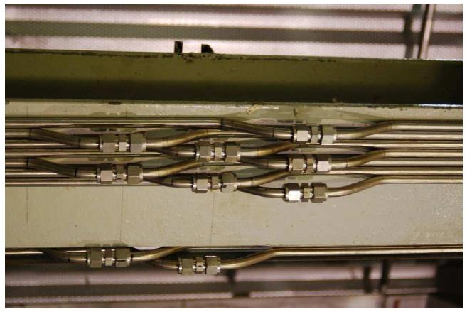
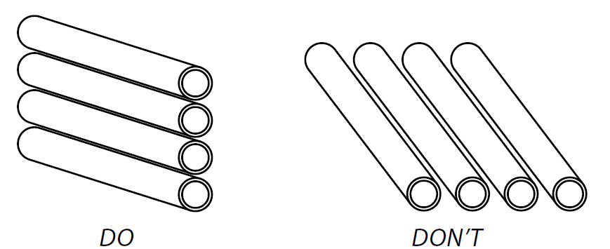
Vertically Gang Tubing
To the maximum extent possible, tubing should be ganged vertically rather than horizontally. Vertical ganging prevents the collection of dirt or any potentially corrosive medium. Vertical ganging additionally increases system safety, since, for example, floor-level horizontally ganged tubing may be stepped on.
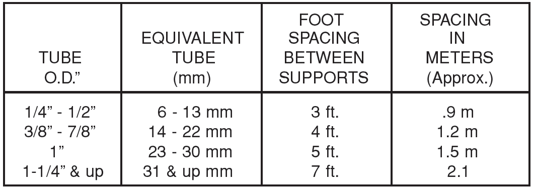
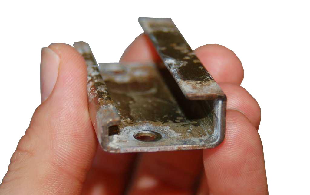
Tube Clamping
When tubing is left unsupported, shock and vibration will cause the tubing to shake, and in turn, cause the fitting to loosen and leak or even allow tube to fail through fatigue. Tubing can be clamped individually, in sets, and can also be stacked.

Tube Clamp material: Polypropylene
Below you will find a chart of recommended spacing between clamps.
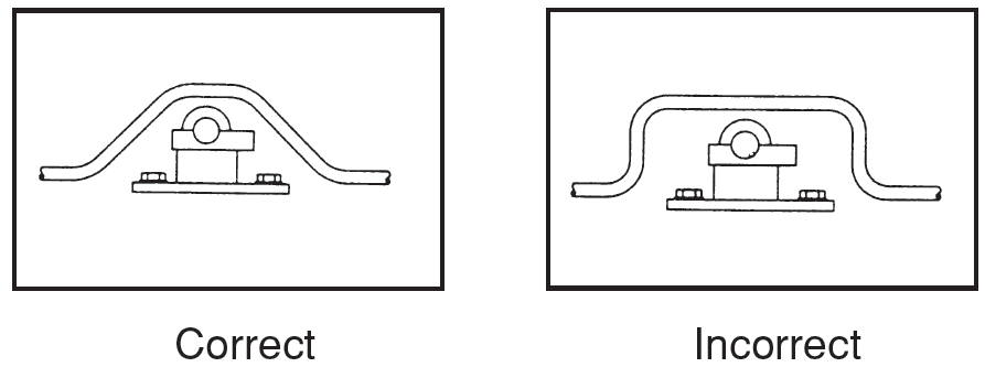
Clamp as close to each bend of the tube as possible; and you must clamp each side.
This eliminates thrust in all directions.
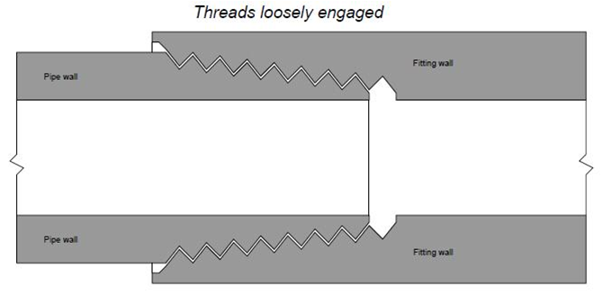
Threaded Joints
Tapered thread pipe fittings
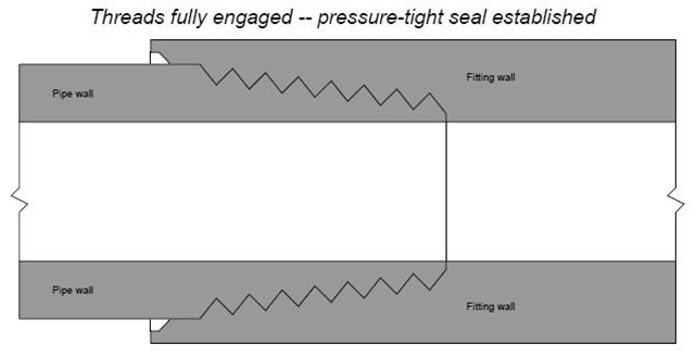
For smaller pipe sizes, threaded fittings are more commonly used to create connections between pipes and between pipes and equipment (including some instruments). The intent of a tapered thread is to allow the pipe and fitting to “wedge” together when engaged, creating a joint that is both mechanically rugged and leak-free. When male and female tapered pie threads are first engaged, they form a loose junction:
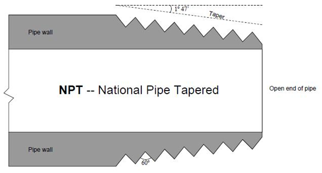
NPT -National Pipe Taper is a U.S. standard for tapered threads used to join pipes and fittings. The taper on NPT threads allows them to form a seal when torqued as the flanks of the threads compress against each other.
NPT fittings must be made leak free with the aid of thread seal tape or
a thread sealant compound.
Thread Tape
Thread tape acts as a lubricant allowing more thread engagement,
preventing galling, and filling the gap between the crests and roots
of mating taper threads in order to prevent formation of a spiral leak path.
Wrap the tape in the direction (clockwise) of the thread.
Draw the tape tightly around the thread, ensuring, at a minimum, one complete
wrap of the tape, (1¼ turns is recommended)overlapping slightly.
Be sure the tape does not overhang the first thread otherwise the tape could
deteriorate and contaminate the fluid system.
On stainless steel a double wrap is recommended to minimize
any possible galling, while providing a good seal.
Parallel thread pipe fittings
An alternative to tapered threads in pipe joints is the parallel thread.
In the United States, a common design of parallel-thread pipe fitting
is the SAE straight thread, after the Society of Automotive Engineers
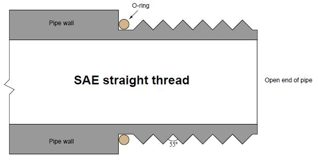
Sealing is accomplished as the O-ring is compressed against the shoulder of the female fitting.
The threads serve only to provide force (not fluid sealing).
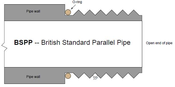
Another parallel-thread pipe standard is the BSPP, or British Standard Pipe Parallel.
Like the BSPT (tapered) standard, the thread angle of BSPP is 55o.
Like the SAE parallel-thread standard, sealing is accomplished by means of an O-ring
;which is compressed against the shoulder of the matching female fitting.
Flanged pipe fittings
Large industrial pipes are joined together by flanges.
A pipe “flange” is a ring of metal, usually welded to the end of a pipe,
with holes drilled in it parallel to the pipe centerline to accept several bolts.
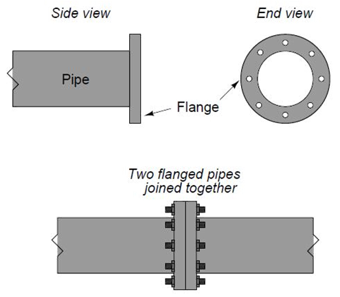
Flange joints are made pressure-tight with a gasket between the
flange pairs prior to tightening the bolts.
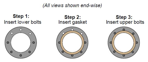
A method of installing such a flange gasket is to first install only
half of the bolts (in the holes lower than the centerline of the pipe)
drop the gasket between the flanges, then insert the rest of the bolts:
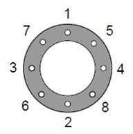
It is very important to evenly distribute the bolt pressure.
This is done by tightening the bolt in a criss-cross sequence.
An illustrative torque sequence is shown in the following diagram
(the numbers indicate the order in which the bolts should be tightened):
Torque wrenches are used for measuring torque during the tightening process.
Another important procedure to observe when working with flanged pipe connections
is to loosen the bolts on the far side of the flange before loosening the bolts on the side
;of the flange nearest you. This is a precautionary measure against the spraying
of process fluid toward your face or body in the event of stored pressure inside of a flanged pipe.
reaching over the pipe to first loosen flange bolts on the far side, if any pressure happens
to be inside the pipe, it should leak there first, venting the pressure in a direction away from you.
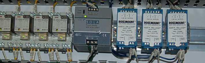
Electrical Signal and Control Wiring
The neatness of assembly in electrical signal wiring is very important.
Neat installations are easier to trace and troubleshoot.
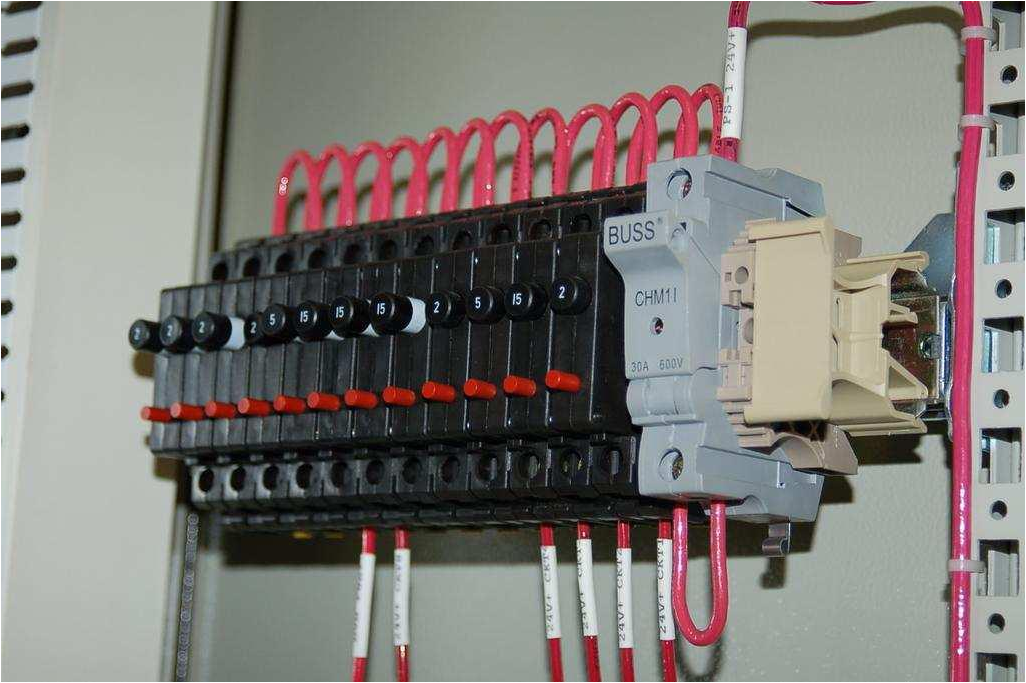
Here we see 120 volt AC power distribution wiring. Note how the hoop-shaped “jumper”
wires are all cut to the same length, and how each of the wire labels is oriented
such that the printing is easy to read:
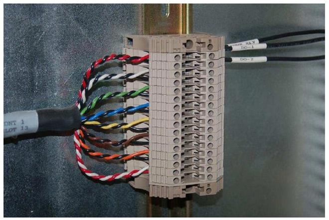
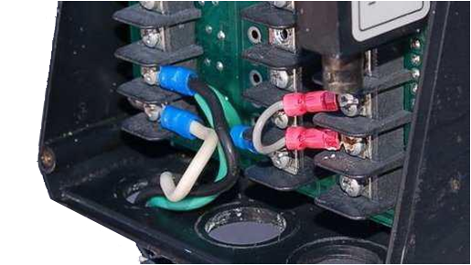
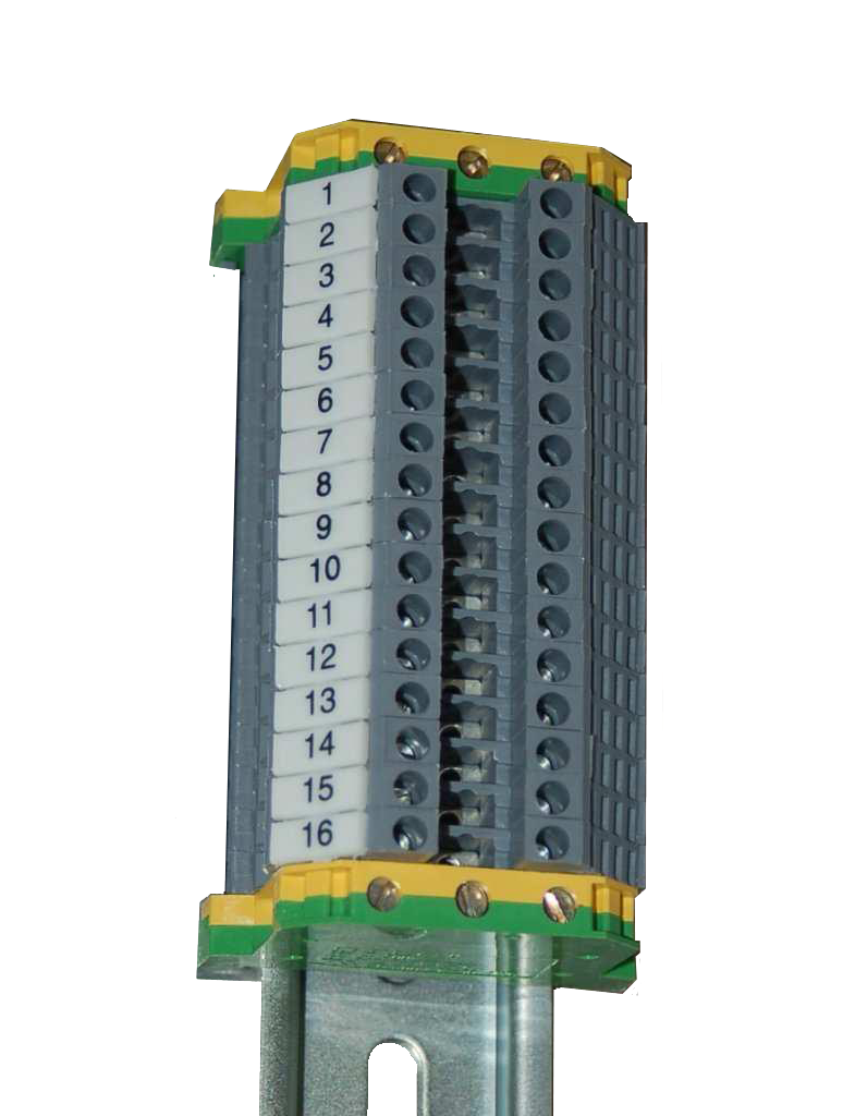
This next photograph shows a great way to terminate multi-conductor signal cable to terminal blocks.
Each of the pairs was twisted together. The end of the cable is wrapped in a short section of
heat-shrink tubing for a neat appearance.
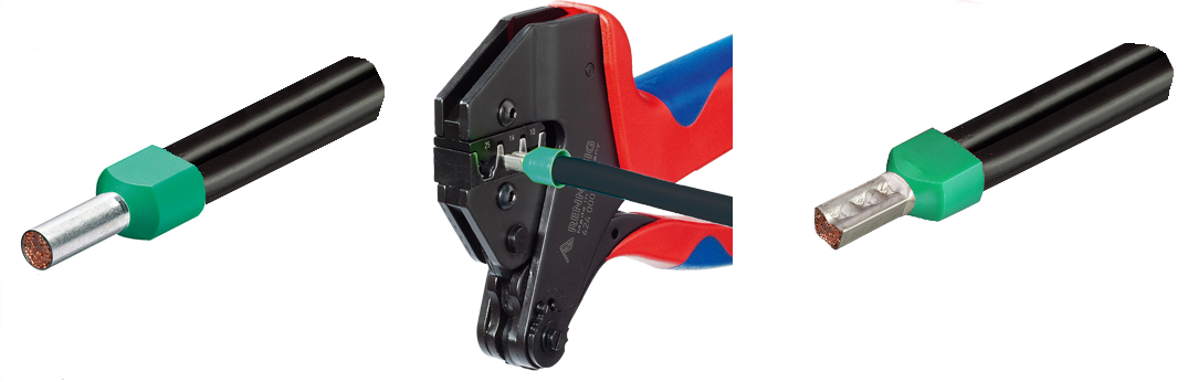
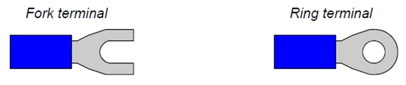
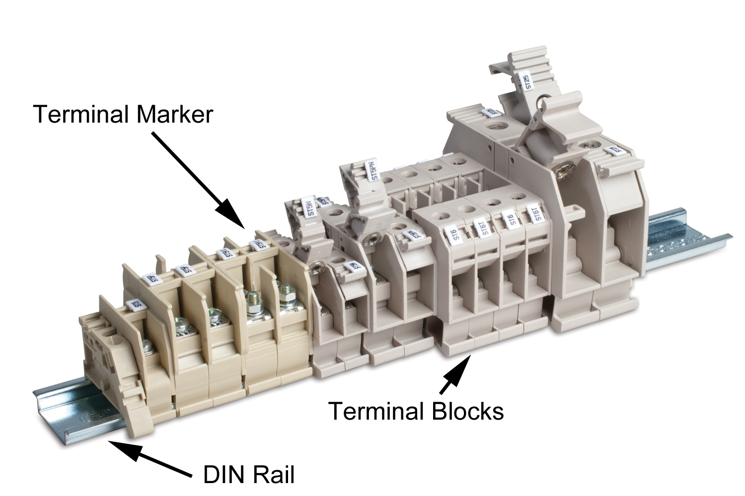
Connections and wire terminations
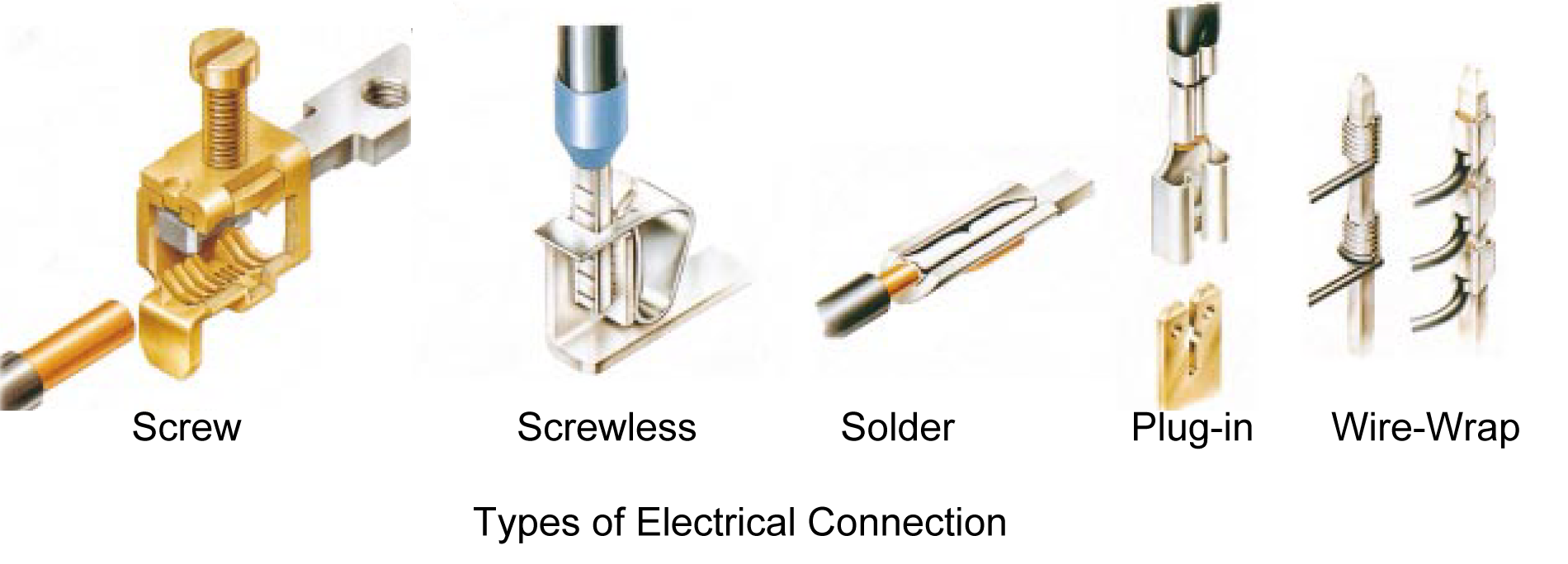
Many different techniques exist for connecting electrical conductors together:
screw, screwless, soldering, plug-in, and wire-wrap are some examples.
Most industrial field wiring connections utilize a combination of compression-style
crimp “ferrules” and screw terminals to attach wires to instruments and to other wires.
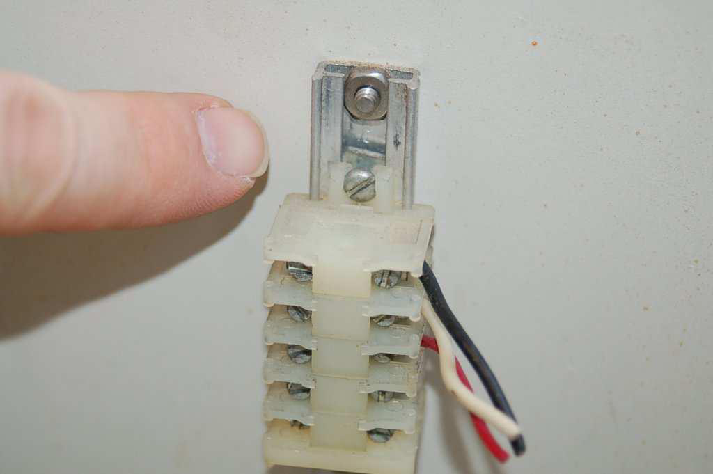
The following picture shows a typical terminal strip or terminal block array
where twisted pair signal cables connect to other twisted-pair signal cables:
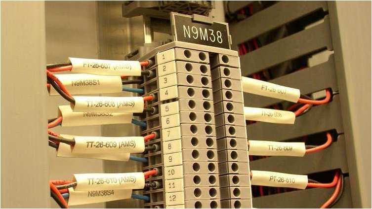
If you look closely at this photograph, you can see the bases of crimp-style compression
ferrules at the ends of the wires, just where they insert into the terminal block modules.
These terminal blocks use screws to hold the wires in close electrical contact
with a metal bar inside each block, but straight ferrules have been crimped on the
end of each wire to provide a more rugged tip for the terminal block screw to hold to.
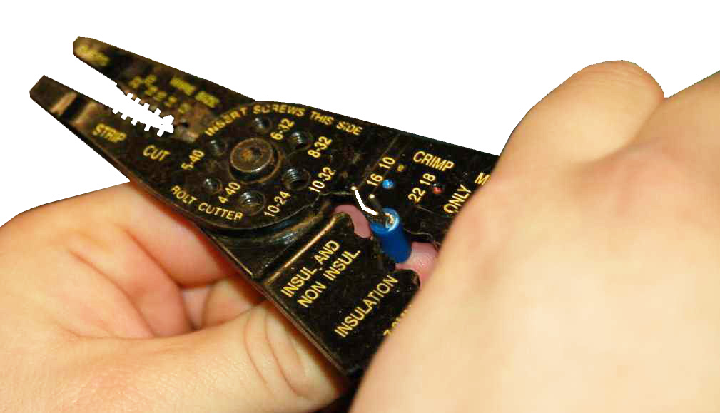
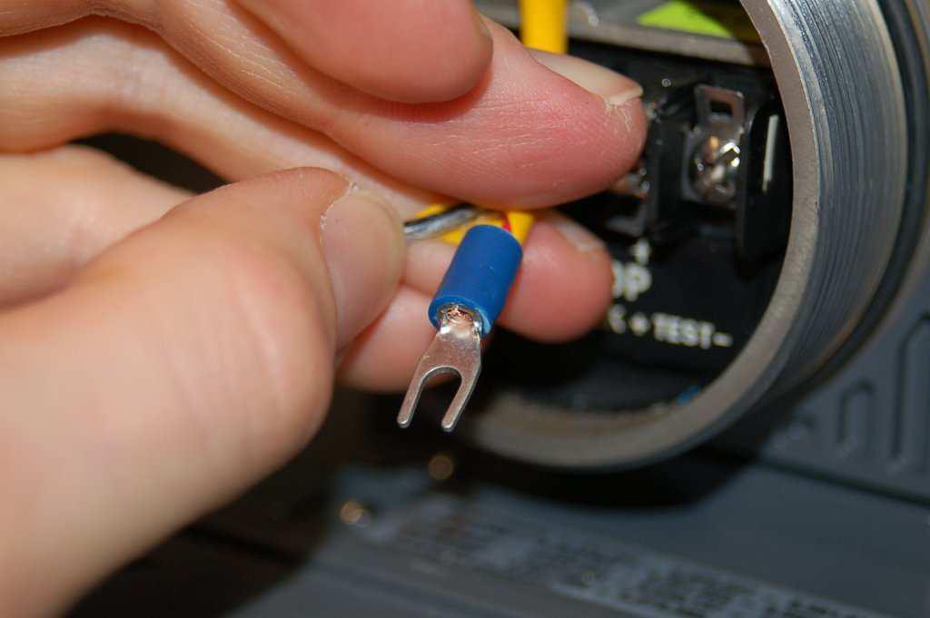
A close-up view shows what one of these straight ferrules looks like:
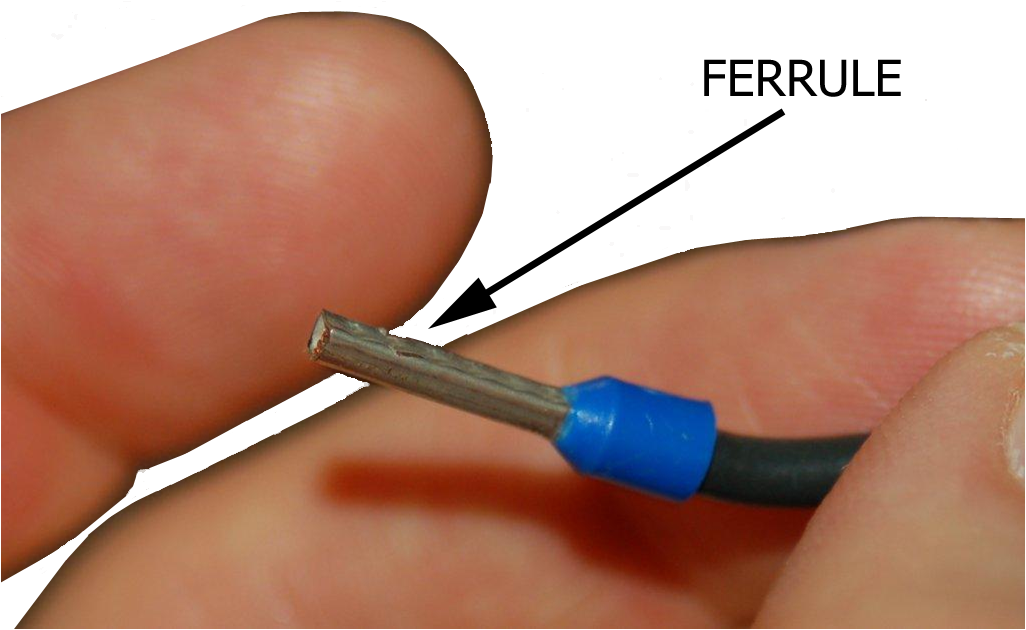
The insulation is removed 1/4" from the tip, inserted into the ferrule and then crimped.
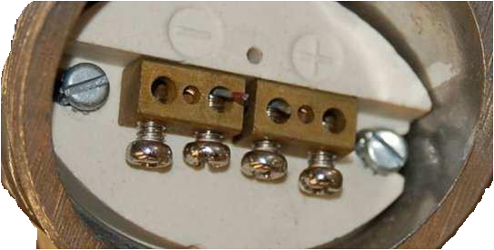
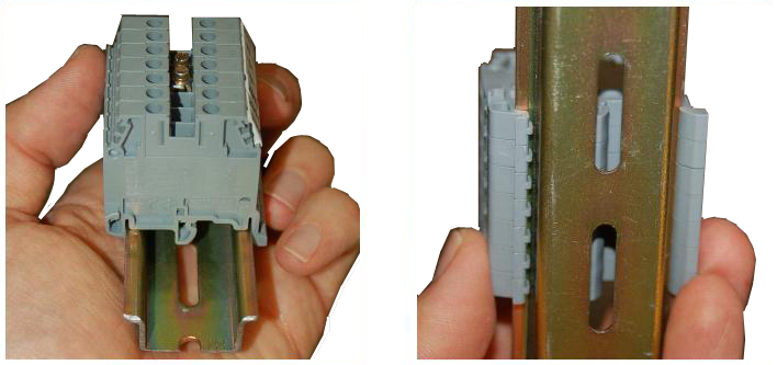
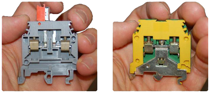
A close-up photograph of a single terminal block module shows how
screw-clamp system works. Into the right-hand side of this block
single wire (tipped with a straight compression lug) is clamped securely.
No wire is inserted into the left-hand side:
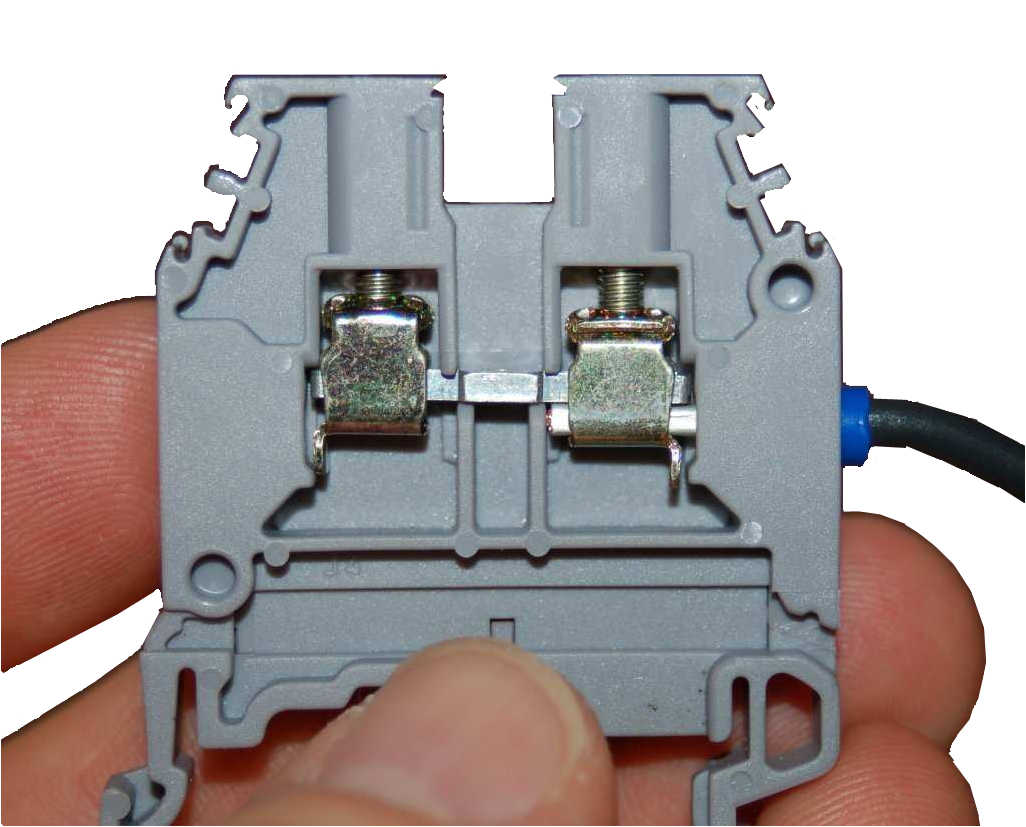
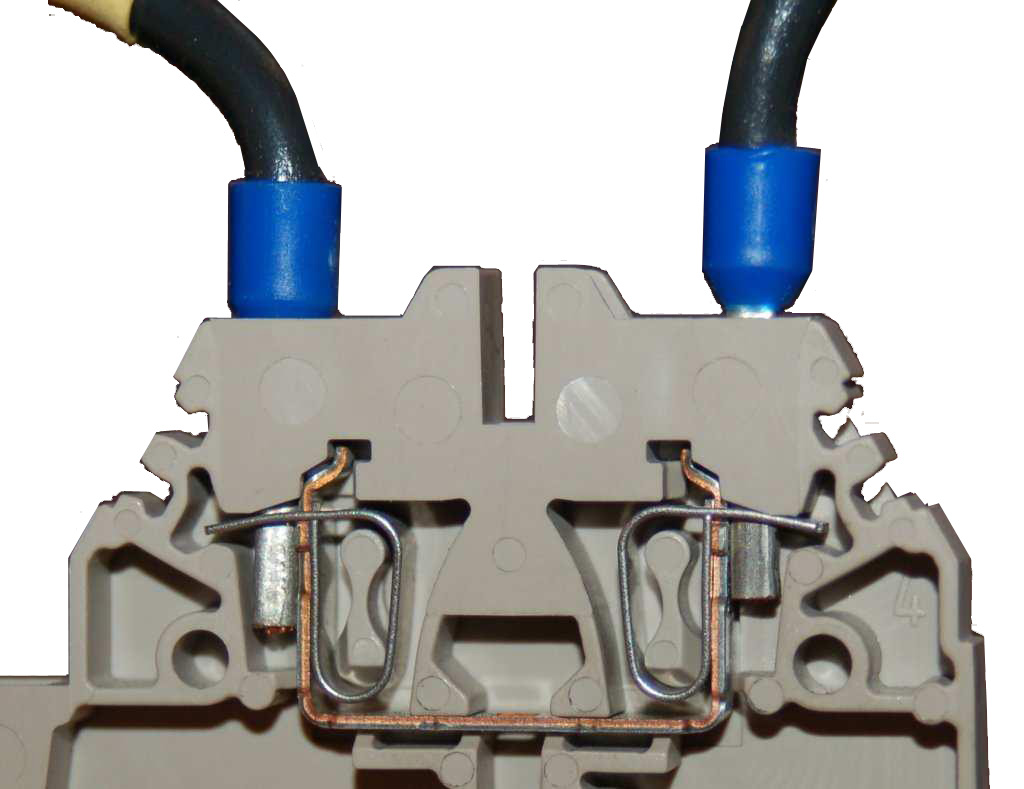
Some terminal blocks are screwless, using a spring clip to make firm
mechanical and electrical contact with the wire’s end.

email: calmansys@yahoo.com